Paul Sagar states that it is an unusually fully charged version of Creo that we are talking about:
“It is, just to put it in context: In the Creo 9 release, we added in the order of 125 improvements. In Creo 10 around 135 improvements and in this release around 150. This is valid proof that we are investing heavily in CAD within PTC, but also that we are actually accelerating the investment in CAD.”
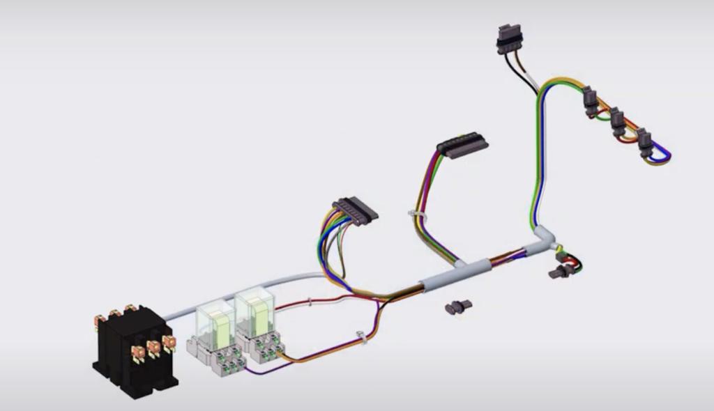
Broaden cabeling and ECAD support
He further notes that, as with most releases, there are different themes around what PTC invest in and why.
“Yes, and Creo 11 is no exception. We have done extensive work on general usability and general productivity. This is about things that more and more of our customer companies are looking at today, not least from a sustainability perspective. Here our improved electrification solutions are important, but also generally about how to develop and build solutions from a sustainability perspective, where things like more electronics and more electrical elements as well as simulation gain space in design.”
In line with this Sagar claims that PTC continues to broaden cabeling and ECAD support compared to version 10.
“We’ve modernized the remove location capability. Locations are when I’ve got a cable that’s routing through an assembly. There are certain key locations along the way. If I want it to go through a hole I want to make sure that the cable passes through this point, etcetera. So, we have the ability to go and view those locations and modify or remove them. We’ve modernized that capability and by doing so we now give the users more graphical interface feedback. You can view those locations in the graphics area and manipulate them there. And you have the ability to filter for all those locations as well.
“Moreover, in Creo 10, we introduced a new cabling tree to give clearer visibility into cabling structures. We’ve now added that or enhanced that in 11 as well. Not only have you got the the cables, the bundles, the harness defined in the tree, but you’ve also got your ancillary add-on like cable ties.”
The same goes for the composite design capabilities introduced in Creo 10, a set of capabilities required as more and more companies want take advantage of the composites in their design with materials such as carbon fiber, Kevlar and others whose advantages are above all lightweight strength.
With Creo 11, PTC continues to invest in these pieces.

Model-Based Definition: A key factor for the digital thread
Another area of great and growing importance is model-based definition (MBD):
“Exactly,” says Sagar, “and the fact is that most of our customers want to change their business and start taking advantage of the digital thread, and as MBD is a key factor in this, consequently we continue to invest heavily here.”
Why is model-based definition so important? Above all, because MBD is a way to produce 3D models so that they contain all the data needed to define a product. For years, engineers have used 2D drawings to deliver product manufacturing information—even when designing models in 3D.
Using model-based definition methods, engineers embed product data directly into the 3D models, creating a single, trusted source of truth for the entire extended team that prevents errors and saves time for everyone.
“With MBD, the model becomes the source that drives all engineering activities. This model can also be used downstream by suppliers and across organizations within a company,” sums up Sagar.
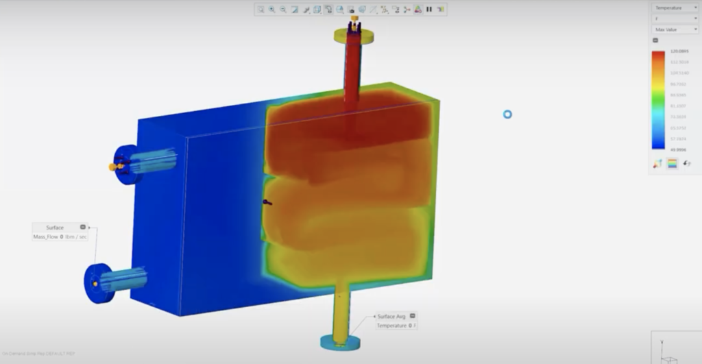
The partnership with Ansys is a mirror of simulation’s growing importance
Another factor that has risen to the top in terms of product design and development is simulation and analysis. This page has also received sharpened functionality in Creo 11. What is interesting here in general is that PTC has chosen to lean on the solutions of the market and technology-leading CAE player Ansys, whose Discovery Live concept is an integrated part of Creo.
“PTC has a very, very strong simulation-driven design strategy with our partnership with ANSYS and we have continued to invest and expand our simulation capabilities,” comments Paul Sagar.
“We leverage ANSYS technology directly embedded in CREO. This is real time simulation capability inside CREO. Here, among other things, we’ve added conjugate heat transfer. This allows you to now go and accurately simulate or predict heat transfer between solid and fluid as it goes through a design. When fluid is running through a fluid channel the software shows me what the heat transfer is of my heat syncs within my design,” he continued adding that, “PTC also made improvements to some of the results whether it be from structural, fluid, or thermal results. Notably they have also updated to the latest analysis solvers.”
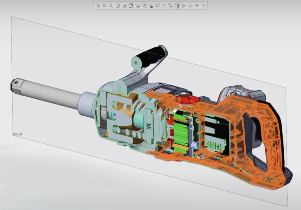
• Copy all bodies from the source part to the target part as separate objects. The resulting body name, material, parameters, and construction attributes are passed for each body.
• Merge all bodies from the same source part. Each resulting body represents the solid geometry of a source part. The resulting body name is the name of the source part. Materials, parameters, and construction attributes are transferred from the first body in the source part.
• Merge all bodies from all source parts.
All resulting geometry is added to a body. The ”Body Option” tab becomes available to add the resulting geometry to an existing body or to create a new body.
The most important enhancements in Creo 11
This is how Paul Sagar summarizes the most important improvements in Creo 11:
• Usability and productivity: Investments in the core modeling environment include support for multibody concepts, streamlining of part design workflows, an upgraded enclosure volume feature for optimal packaging solutions, and a refined Shrinkwrap feature for seamless assembly management. A Shrinkwrap model is a part composed of a collection of surfaces that represents the exterior shape of a source model. You can use a part or an assembly as the source model for a Shrinkwrap. These models usually reduce disk and memory usage by more than 90 percent.
“Some other examples around productivity and some general usability improvements that we’ve made cover the model tree around expanding collapse behavior, altering some of that, reflecting general behavior of what happens when you expand or collapse. Now, you can incrementally expand or incrementally collapse certain nodes in the tree. And then we did some improvements around renaming, just making it more efficient for the user to be able to rename their problem and their features in the model tree.”
“Moreover, selection is one of the most important things you do in any 3D system,” Sagar went on and added, “Before you do anything, you got to select something that you want to do an operation on. So, we’ve made some improvements to our selection for a number of years. We’ve had box selection available inside the product, but it was only available in certain areas, so we’ve now made that common and expanded it throughout the whole product. Anywhere where you do surface-based selection, you can now select surfaces based upon a box.”
”There’s much more than these, but they are good examples of enhancements we’re doing.”
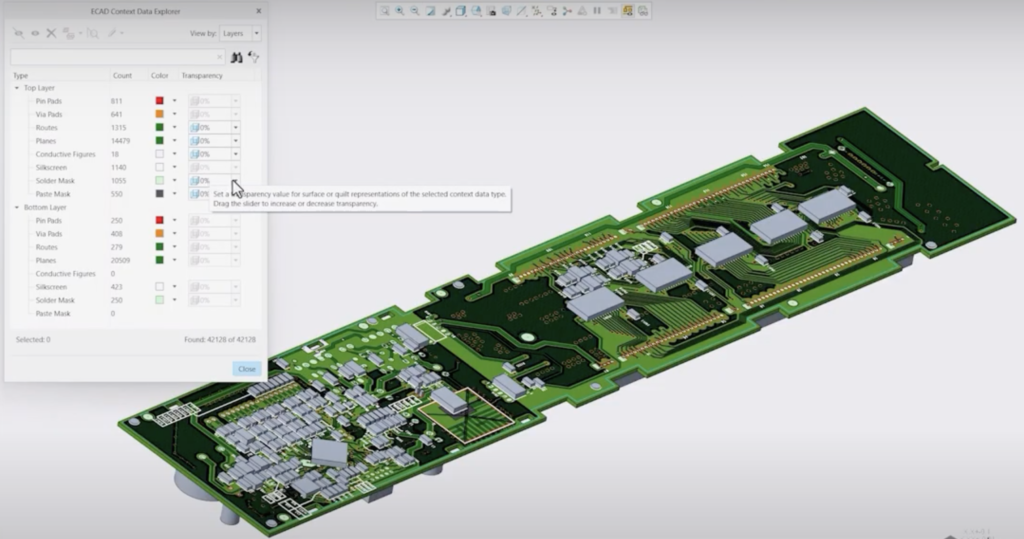
• Improvements to the electrification tools: Enhanced capabilities in cabling and ECAD-MCAD collaboration are in line with the growing importance of electrification in various industries. Customers can use cable tools to precisely manipulate locations, place custom components more efficiently, and gain greater visibility into cable network structures. Additional ECAD features that improve transparency controls in PCB stack-ups.
• Sharpened tools for composite design and manufacturing: Advances in composite design, simulation and manufacturing capabilities for tsets to meet the needs of design engineers who are increasingly using composite materials. The software includes improved tools for the design and fabrication of composite structures. These improvements address the unique challenges that composite materials present, such as layout strategy optimization and weight reduction without compromising strength.
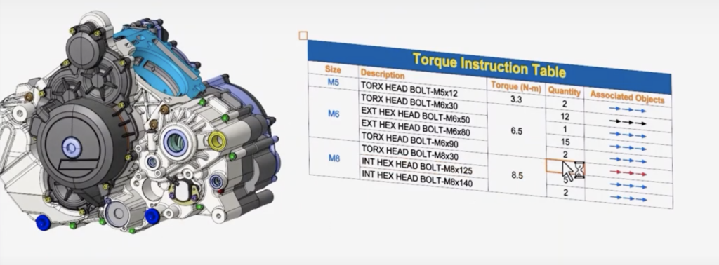
• More comprehensive Model-Based Definition (MBD) tools: Model-Based Definition has also received a major boost in Creo 11. With expanded MBD tools, users can now embed more detailed design information directly into the 3D model. This feature helps reduce reliance on traditional 2D drawings and supports more effective communication between teams and throughout the product development lifecycle. More powerful model-based definition tools enable teams to organize simple design data into simple human- and machine-readable tables with user-defined text, parameter texts, and semantic references.
• Simulation-driven and generative design: Simulation-driven design and generative design are hallmarks of modern CAD systems, and Creo 11 excels in these areas. Designers can leverage simulation insights early in the design process and guide decisions that lead to innovative and performance-optimized solutions. Creo 11 introduces new simulation-driven design capabilities for better design ideas, guidance and validation.
Creo’s generative design has been enhanced with minimum feature size limits, layer loading support, and plane symmetry constraints. Generative design features enable the exploration of many design iterations and leverage computational power to discover new and efficient forms.
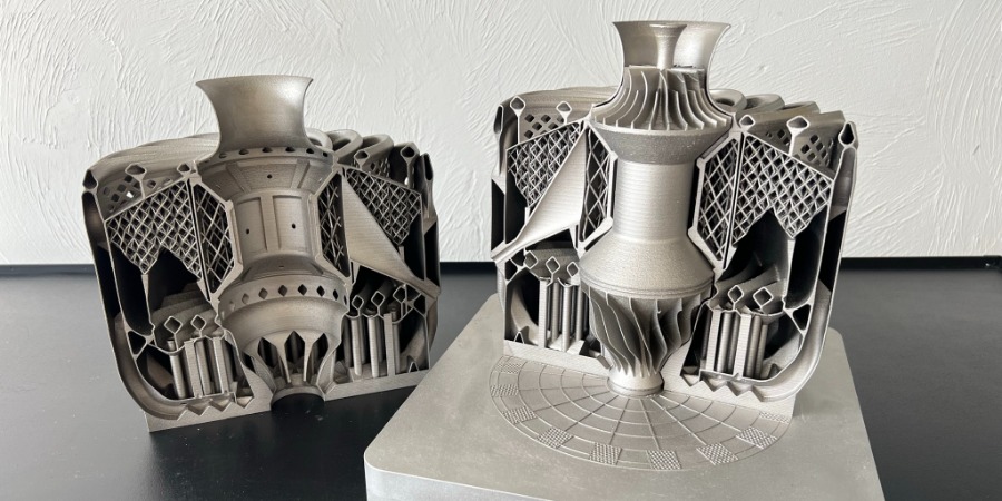
• Advanced Manufacturing Tools: Advanced manufacturing tools are another piece of the Creo 11 puzzle, demonstrating PTC’s commitment to not only design, but manufacturing excellence. The software caters to the latest manufacturing technologies, including additive manufacturing, ensuring compatibility with the latest production technologies. Optimized additive and subtractive manufacturing tools ensure greater efficiency and versatility in the manufacturing process. Improvements include improved mesh texture creation and smoother operations, such as 4-axis rotary milling and surface turning.
“We continue to invest in manufacturing, both with additive manufacturing tools and the progress we’re making there as more and more of our customers want to take advantage of 3D printing manufacturing for end production, but also at the same time continue to expand our subtractive manufacturing capabilities as well,” says Paul Sagar.
In addition to the release of Creo 11, PTC announced the latest version of Creo+. The point of Creo+ is that it is a SaaS CAD software solution, with cloud-enabled collaboration and rights tools. Creo+ is fully backward compatible with local versions of Creo and is built on the same core technology as Creo, so no data translation is needed.
Of course, Creo 11 also includes all features from previous Creo versions.


